Every interrupted-spiral hypotube in the catalog
carries three numbers under Cut pattern: pitch, degrees cut and uncut, and cuts per
revolution. Between them they fix how much wall is open, how much is bridge, and
where the bridges fall. This is what each one does, shown on fifteen parts of a
single 1F tube.
Stratos Laser Engineering · 4 September 2026 · 6 min
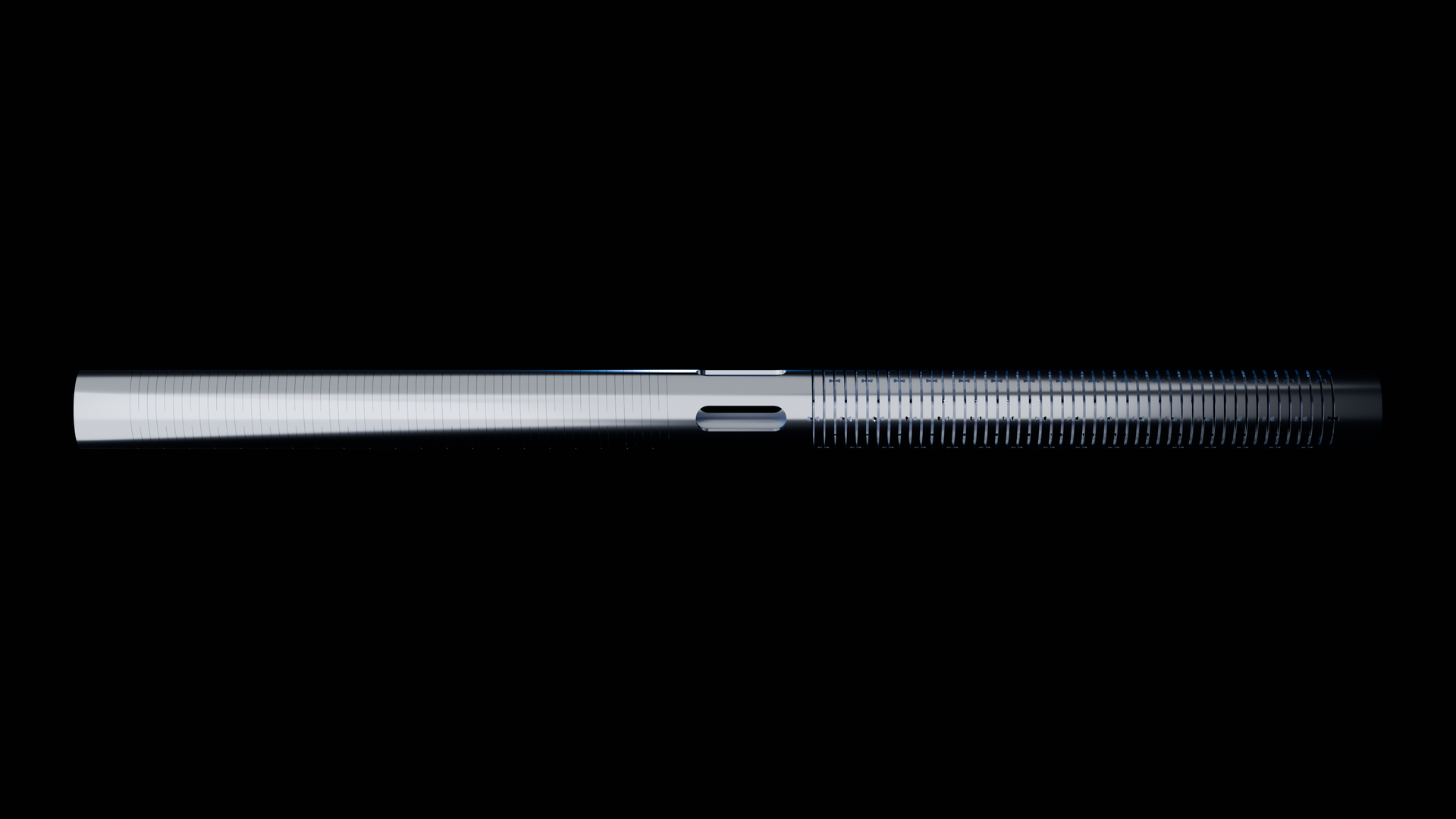
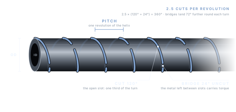
The spec on the tube. 120° cut, 24° uncut at 2.5 CPR. Pitch is the axial advance per turn; each turn is split between open slot and the bridge that carries torque.
Pitch
Pitch is the axial distance the helix advances in one revolution, 0.005 in to
0.025 in across the catalog. It sets how many turns of pattern fit in an inch: 200
at 0.005 in, 40 at 0.025 in. More turns per inch means more slot per inch and a
tube that bends on a smaller radius. It also means more bridges per inch, and at
the shortest pitches the bridge count is what carries push and keeps the tube from
stretching.
Degrees cut and uncut
Around one revolution the laser cuts an arc, lifts, leaves a bridge, and cuts
the next arc. 120° cut and 24° uncut means each slot spans a third of the
circumference and each bridge a fifteenth. The cut share is the flex: 120° of every
144° is open. The uncut share is the torque and the hoop strength: those 24°
bridges are the only metal joining the turns. 65° cut and 15° uncut opens less than
half of each 80°, so the tube is stiffer in bending and stronger in torque with the
same pitch.
Cuts per revolution
CPR is how many cut-and-bridge pairs fit in one turn: 2.5, 3.5 or 4.5 in the
catalog. Multiply out and the rhythm closes: 2.5 × (120° + 24°) is 360°. The
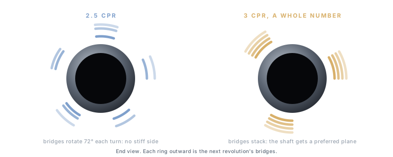
fractional CPR is deliberate. With 2.5 pairs per turn the bridges land half a pair
further round on every revolution, so no two bridges stack on the same clock
position and the tube has no preferred bending plane. A whole-number CPR would put
every bridge in a line and give the shaft a stiff side.
Why the half. Each ring outward is the next revolution's bridges. Fractional CPR spreads them round the tube; a whole number stacks them and the shaft gets a stiff side.
Fifteen parts, one tube
The 1F family below is one tube, 0.014 in OD × 0.0105 in ID, 6 in long, cut
fifteen ways. Three rhythms across, five pitches down. The bend radius is the
per-joint contact model for 304 stainless, the figure each product page marks
experimental.
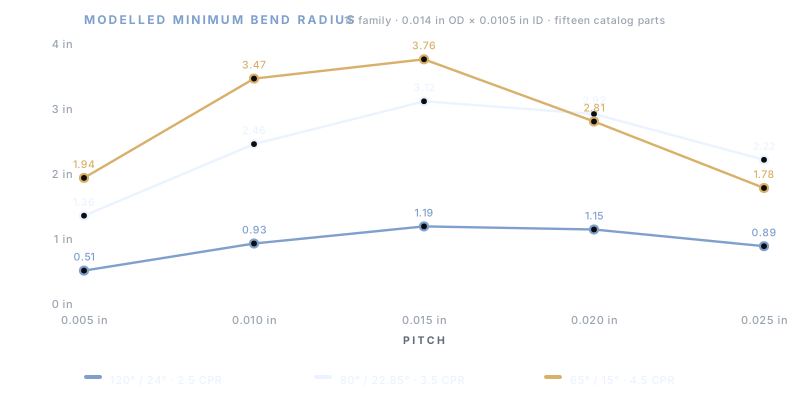
Modelled minimum bend radius. Each cell is a catalog part; click through for the print and the 3D model. All fifteen are $200.
The table as a chart. The rhythm sets the band; the pitch moves along it; past 0.015 in the model turns back down.
Reading the table
Across a row the rhythm does the work. At 0.005 in pitch the 120° cut bends on
0.51 in and the 65° cut on 1.94 in, nearly four times the radius from the same tube
and the same pitch, because the bridges went from a fifteenth of the turn to nearly
a fifth of it. Down the first three rows the pitch does the work: doubling pitch
from 0.005 in to 0.010 in halves the slots per inch and the 120° radius goes from
0.51 in to 0.93 in.
The last two rows are the interesting ones. Past 0.015 in the modelled radius
stops growing and turns back down. At long pitch the slots are far apart and each
joint must take a larger share of the total bend; the contact model finds the slot
faces touching sooner, so the minimum radius the tube reaches before the slots
close is smaller again, while the tube between joints is now stiffer. Two parts
with the same minimum radius can feel very different in the hand, which is why the
radius is guidance and the bench is the decision.
Setting the numbers
For a shaft that must steer, start at 120° / 24° and pick the pitch for the
radius you need. For a support section that must push, move to 65° / 15° and
lengthen the pitch. For a tip that must track, shorten the pitch first, then open
the cut. Order the three rhythms at one pitch, bend them, and the next pitch is
obvious.
Order the row
The 0.005 in row, three parts, $600, 6 in each: SL-049470,
SL-049480 and SL-049490.
The same three rhythms exist at every catalog size from 1F to 27F.