A laser-cut hypotube is one piece of 304
stainless tube with a pattern of slots in its wall. The slots decide everything the
shaft does: how far it bends, how much of a turn at the hub reaches the tip, and
whether it kinks. Three patterns cover most catheter shafts, and each one trades
torque for flex in a different place.
Stratos Laser Engineering · 4 September 2026 · 7 min
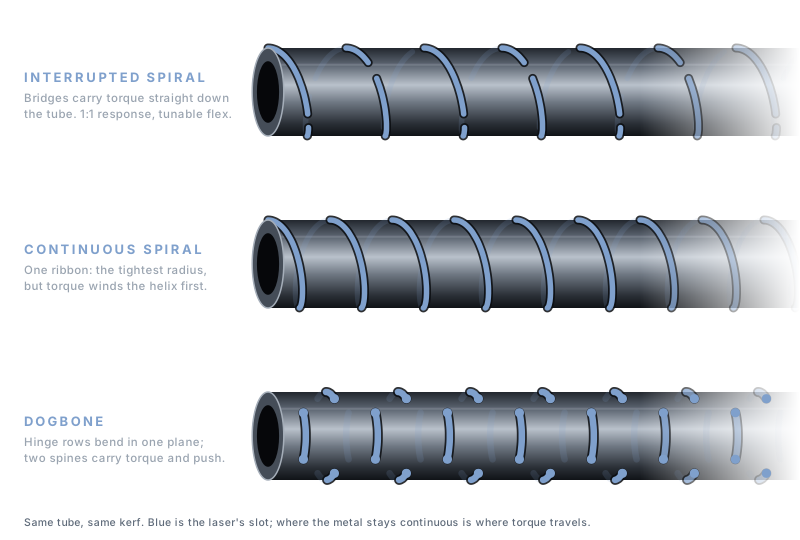
The three patterns on the same tube. Blue is the laser's slot; where the metal stays continuous is where torque travels.
The torque path
Torque travels through whatever material is still continuous around the
circumference. In a plain tube that is the whole wall, and the twist per unit
torque is set by the polar moment of the section, which grows with the fourth
power of diameter. Every slot the laser cuts removes part of that path. The
pattern's job is to remove enough wall to let the tube bend while leaving a
continuous route for torque. Where the route is continuous and short, the tip
follows the hub. Where it winds or breaks, the tip lags.
Interrupted spiral
A helical cut that stops and restarts on every turn, leaving an uncut bridge
each time. On a catalog part the rhythm is written as degrees cut and degrees
uncut per bridge, at a number of cuts per revolution: 120° cut and 24° uncut at
2.5 CPR, or 65° cut and 15° uncut at 4.5 CPR. The bridges are the torque path.
Because they sit at different clock positions on successive turns, the tube has no
continuous helical hinge, so torque goes straight down the length instead of
unwinding a helix. That is why the interrupted spiral is the shaft pattern for 1:1
torque response, and it is the pattern behind every one of the 262 hypotubes in
our catalog.
Flex comes from the slots. A longer cut angle and a shorter pitch put more open
slot per inch of tube and the shaft bends on a tighter radius. On our 1F family
the modelled minimum bend radius runs from 0.51 in at 120° cut, 0.005 in pitch, to
3.76 in at 65° cut, 0.015 in pitch, in the same tube.
The next note works through those
numbers.
Continuous spiral
One unbroken helical cut from end to end. The tube becomes a ribbon wound on
itself, so flex is progressive and smooth and the bend radius can be very small.
The cost is the torque path: it now runs along the helix, and torque applied at
the hub first tightens or loosens the coil before it rotates the tip. The lag is
small on a short section and grows with length. Continuous spirals earn their
place at the distal end, where the shaft has to follow a tortuous vessel and a few
degrees of lag matter less than the radius it can take.
Dogbone
Pairs of opposed slots with a bridge between them, repeated along the tube and
often rotated 90° every row. Each row is a hinge, so bending is planar: the shaft
bends easily about one axis and resists the other. Two spines of uncut material run
the length of the tube and carry torque and push. Dogbone patterns are the choice
for a deflectable section that must bend in one plane under a pull wire, and for
the steering segment of a delivery system. Our engineers also mix them: a dogbone
zone with its spine rails leading into an interrupted spiral on the rest of the
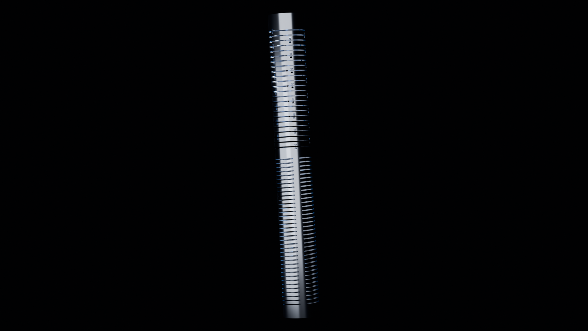
shaft, on one piece of tube. The render behind this page's title is exactly
that part.
Against a braid
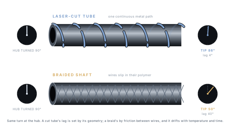
Torque lag. Same 90° at the hub. The cut tube's lag is set by geometry alone; the braid's by friction between wires and the polymer around them.
A braided shaft transmits torque through friction between wires and through the
polymer that encapsulates them. Both slip a little under load. On a 135 cm
neurovascular catheter that slip adds up to tens of degrees of rotational lag
between hub and tip, and it changes as the polymer creeps with temperature and
time. A cut tube has no wires to slip against each other. The torque path is the
same metal from end to end, and lag is set by geometry alone, so it is the same on
the hundredth device as on the first.
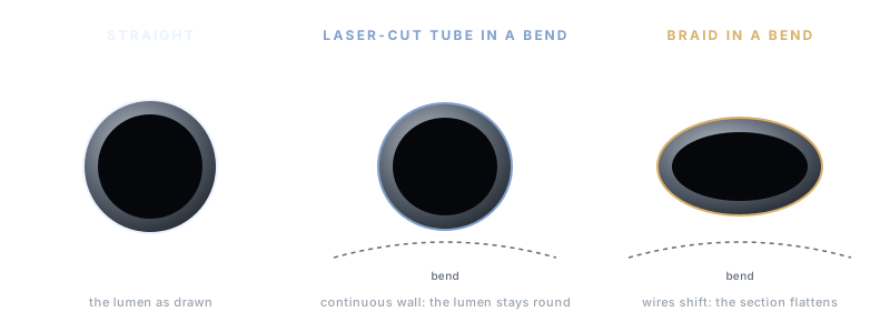
Ovalization. A continuous wall keeps its hoop strength through the bend; shifting wires flatten the section and the lumen with it.
Braids also ovalize. Under a bend the wires shift and the round section
flattens, and the lumen with it. A cut tube keeps a continuous wall between slots,
so its hoop strength is the tube's own and the lumen stays round through the
bend.
Against a coil
A coil is the continuous spiral taken to its limit: a wire with no bridges at
all. Its flexibility is excellent and its torsional stiffness is orders of
magnitude below a tube of the same size, because the whole load path is a spring.
Coils belong where the shaft only has to flex and something else carries the
torque.
Choosing
Start from what the shaft must do at each station along its length. Where it
must steer, the interrupted spiral. Where it must track through the tightest
anatomy and nothing rotates, the continuous spiral. Where it must deflect in one
plane, the dogbone. Then set the numbers, and the fastest way to set them is to
bend real parts.
Bench it with catalog parts
The three interrupted-spiral rhythms of one size, so the difference is the
pattern and nothing else. Each is $200, 6 in long, 304 stainless, with a 3D
model and an engineering print on its page.
A geometry that is not on the shelf, or a mixed pattern along one tube, is a
custom cut: send the numbers the part has to hit and our
engineers design the pattern and write the program. Prototypes leave in two to
three days.